Hi,
Thinking of doing mods on my 2 cdps.
- NAD C542 - In Manila
Marantz CD6003 - Here in Singapore
Pls. pm me what is the best mod to be done in either cdp and the cost.
Thanks,

As an example, I would like to show an approach on how to modify the Marantz CD-6003 CDP.

As a start, let's try to gather some data on this CDP.
From the link,
http://www.cyberselect.co.uk/product/14461. It is using the Cirrus Logic CS-4398 D/A converter. This is the same converter used on the Marantz CD-6002.
2. It is using
"The Marantz HDAM-SA2 - Hyper Dynamic Amplifier Modules - replace single chip, 'off-the-shelf' Op-Amps, operating as a buffer amplifier and as a Low Pass Filter."
Based on this, it appears that the output analog section is using some proprietary circuitry (HDAM) for its active low pass filter circuit.
This will have to be verified by reverse engineering the circuit board of the CDP.
With this information, we should start by geting hold of the datasheet for the Cirrus Logic CS-4398 D/A converter and studying it from the link,
www.cirrus.com/en/pubs/proDatasheet/CS4398_F1.pdf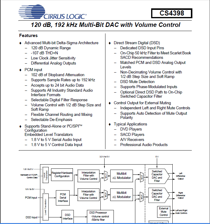
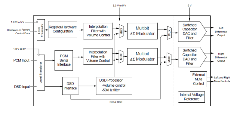
Based on this, it appears that:
a. It has its own digital filter and own voltage reference
- this is typical for modern DACs, previously external digital filters were employed
-- It's internal digital filter can operate in 3 oversampling modes based on the input sample rate. Based on feedback that less oversampling results is subjectively better sound, we should operate with minimal oversampling as possible. As such, we should operate at quad speed mode.
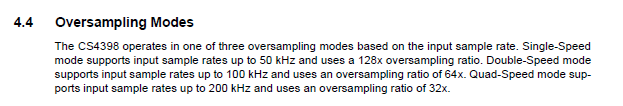 So, our very first mod (should we decide to pursue it and is not implemented on the CDP circuit board) is making the D/A converter operate at quad speed mode.
-- Further since it has an internal voltage reference, it is a good idea to ensure that the DAC operates at a stable temperature.
Why?
Many precision test instruments have voltage references which are "ovenized". Meaning to say, it is enclosed in a metal receptacle to ensure that the surruounding temperature is uniform and as such would result in a fixed reference value. It is then essential or a must (necessity) for D/A converters!!! For obvious reasons, the internal voltage reference would have fluctuating reference values should the surrounding temperature change.
So, our second mod is to put a heatsink on the D/A converter (if one does not exist already). Just make sure you use a thermal adhesive with good thermal coefficient to help ensure that heat can easily be absorbed by the heatsink. Also, make sure that the heatsink fills up the whole D/A converter package.b. Decoupling capacitors as close as possible to the D/A converter is a must.
"The Typical Connection Diagram shows the recommended power arrangement with VA, VD, VLS and VLC connected to clean supplies. Decoupling capacitors should be located as close to the device package as possible."
So, our third mod is to ensure that the decoupling caps are as close as possible to the D/A converter.c. The datasheet also recommends a second order Butterworth filter based on application note 48.
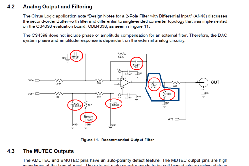
On the 2 items highlighted in blue, based on the recommendations from the picking capacitors article by Walter A. Jung and Richard Marsh
We should observe their recommendations.
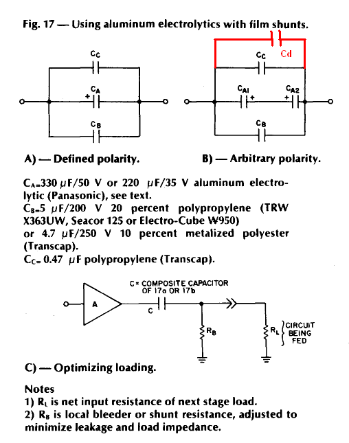 So, our fourth mod is as below:
Based on experience, I have gone with the arbitrary polarity configuration (B). If I observed that the original output coupling capacitor is 22uF, here is what I do
- Ca1 and Ca2 is a low ESR 47uF or 56uF electrolytic capacitor
- Cb is a polypropelene capacitor from 1uF to 2.2uF
- Cc is a polypropelene capacitor from 100nF to 220nF
- I add a Cd which is a polypropelene capacitor from 1nF to 10nF
For the local bleeder or shunt resistance I usually place anything from 1Kohm to 4.7Kohm.For the rest of the capacitors encircled in red,
- Ceramic COG should be replaced with polyester (mylar) capacitor or polystyrene capacitors (you should find these in all Alexan branches or Watsons Electronic store in Raon)
- the 100uF electrolytic capacitor should be any low ESR capacitor such as Nichicon "PL", "PM", "HD"; Rubycon "ZL" etcI hope this helps


