Author Topic: Biasing Dynaco MK3 & which KT88 brand best fits for a hi-fi application?  (Read 36461 times)

0 Members and 1 Guest are viewing this topic.

Offline Tube Pro

  • Trade Count: (0)
  • Collector
  • **
  • Posts: 138
  • It occupied 1,500 square feet and weighed 40 tons:
  • Liked:
  • Likes Given: 0
Hello to all tube experts, and tube diy'ers.
I am about to start building my 1st tube amplifier and plan to make a PP Dynaco MK III rated 60 watts power output with the KT88 pair of tubes.
Just got confused when I read a portion from the procedure of its "Initial Adjustment" or the bias setting, on the manual i've downloaded online, that after warming up the tubes (which means line cord already plugged in to AC outlet without the tube rectifier (GZ34) sitting on its socket for several seconds), plug in this rectifier tube is the next step and will allow voltage readings (in about 10 seconds) from KT88's pin # 8.
As I am in the solid state amp assembly and my first time in this tube thing, is it really safe to plug in this rectifier tube without turning the unit Off first after the warming up procedure?  ???
Or the manual just missed some part of the instruction to turn it off first and proceed to inserting the recti tube?
It is in page 11 continued from page 10 of the 16-page vintage manual.
Just afraid of doing such thing as I know the secondary AC voltage that will get into the rectifier is 430Vac in each of the 2 plate terminals. :o
If this is just normal to tube biasing, well, can I have some of your professional opinions and suggestions on this?
One thing, can somebody help me decide what practical brand of tube to buy for this project?
Here are my choices:

1. Sovtek (as it seems to be the cheapest among the list)
    which says=> Having great hi-end and lush mids - the Sovtek KT88 was designed to offer the highest output power and the most reliable - linear performance available in a KT88. The low-end is a bit muffled - but not flabby. The unique tri-alloy plate structure of the Sovtek KT88 yields higher minimum plate current and higher transconductance while improving heat dissipation and reducing tube warm-up time.

2. Electro-Harmonix
    => For the KT88EH a new geometry is utilized to reduce odd order harmonics for a sweet top end while the peak power is extended to improve low frequency response. The new glass formula body ensures long life and improved reliability. The perfect choice when the authentic sound is needed.

3. JJ/Tesla
    => JJ has outdone themselves with this tube. The quality of construction and sound is reminiscent of the original GEC KT88. These tubes will work well in Marshall tube amps as a 6550 replacement, Ampeg amps, SUNN amps - any 6550 application.

any other suggestions based on price and quality.
A great pleasure to join your forum and appreciate your help in advance.
UNIVAC: a device, which contained 20,000 vacuum tubes!

Offline romymartinez

  • Trade Count: (+10)
  • DVD Addict
  • ***
  • Posts: 793
  • Hi, I'm new here!
  • Liked:
  • Likes Given: 1
Hi Sir,

Are you building one or two monoblocks?


Offline Tube Pro

  • Trade Count: (0)
  • Collector
  • **
  • Posts: 138
  • It occupied 1,500 square feet and weighed 40 tons:
  • Liked:
  • Likes Given: 0
Hi Sir Romy,

I'll build two monoblocks in a single chassis.
What do you think, do I need 2 power trannies, one for each channel?
UNIVAC: a device, which contained 20,000 vacuum tubes!

Offline Tube Pro

  • Trade Count: (0)
  • Collector
  • **
  • Posts: 138
  • It occupied 1,500 square feet and weighed 40 tons:
  • Liked:
  • Likes Given: 0
hi,

to be specific with the instructions i found in the Dynaco manual, here's the view of the page 10 & 11 consecutively:

Last part of Page 10:

in this 1st part of the biasing, it says plug the unit to AC power in without the rectifier tube to warm up filaments...

First part of Page 11:

...now in this ff step, saying to plug-in the rectifier tube. not saying to turn the unit off first before plugging in the rectifier to its socket.
Is this safe anyway?

 ???
UNIVAC: a device, which contained 20,000 vacuum tubes!

Offline Tube Pro

  • Trade Count: (0)
  • Collector
  • **
  • Posts: 138
  • It occupied 1,500 square feet and weighed 40 tons:
  • Liked:
  • Likes Given: 0
Here are some shots, not all mine, to share of the looks of the Dynaco MK3's inside-out:

First is the manual cover with the top view pic of the amp:
UNIVAC: a device, which contained 20,000 vacuum tubes!

Offline Tube Pro

  • Trade Count: (0)
  • Collector
  • **
  • Posts: 138
  • It occupied 1,500 square feet and weighed 40 tons:
  • Liked:
  • Likes Given: 0
the schematic:


the inside-bottom part with wirings:
UNIVAC: a device, which contained 20,000 vacuum tubes!

Offline Tube Pro

  • Trade Count: (0)
  • Collector
  • **
  • Posts: 138
  • It occupied 1,500 square feet and weighed 40 tons:
  • Liked:
  • Likes Given: 0
the pcb parts placement side labelled with values and bottom side:

UNIVAC: a device, which contained 20,000 vacuum tubes!

Offline Tube Pro

  • Trade Count: (0)
  • Collector
  • **
  • Posts: 138
  • It occupied 1,500 square feet and weighed 40 tons:
  • Liked:
  • Likes Given: 0
the pcb pre amp with the components:


perspective:

« Last Edit: Aug 30, 2009 at 05:12 PM by Tube Pro »
UNIVAC: a device, which contained 20,000 vacuum tubes!

Offline Tube Pro

  • Trade Count: (0)
  • Collector
  • **
  • Posts: 138
  • It occupied 1,500 square feet and weighed 40 tons:
  • Liked:
  • Likes Given: 0
the original Dynaco foil pattern:


the twin module: (component side):

UNIVAC: a device, which contained 20,000 vacuum tubes!

Offline Tube Pro

  • Trade Count: (0)
  • Collector
  • **
  • Posts: 138
  • It occupied 1,500 square feet and weighed 40 tons:
  • Liked:
  • Likes Given: 0
the MK3 with cover:


without cover:

« Last Edit: Aug 30, 2009 at 05:10 PM by Tube Pro »
UNIVAC: a device, which contained 20,000 vacuum tubes!

Offline Tube Pro

  • Trade Count: (0)
  • Collector
  • **
  • Posts: 138
  • It occupied 1,500 square feet and weighed 40 tons:
  • Liked:
  • Likes Given: 0
MK3 top view:
UNIVAC: a device, which contained 20,000 vacuum tubes!

Offline Tube Pro

  • Trade Count: (0)
  • Collector
  • **
  • Posts: 138
  • It occupied 1,500 square feet and weighed 40 tons:
  • Liked:
  • Likes Given: 0
the twin monoblocks Dynaco MK3:


a closer look:
« Last Edit: Aug 30, 2009 at 05:11 PM by Tube Pro »
UNIVAC: a device, which contained 20,000 vacuum tubes!

Offline Tube Pro

  • Trade Count: (0)
  • Collector
  • **
  • Posts: 138
  • It occupied 1,500 square feet and weighed 40 tons:
  • Liked:
  • Likes Given: 0
also, since the non-existence of the Selenium rectifiers nowadays, can the silicon 1N4007 be replaced for the negative bias circuit? (as the silicon type has far more advantages over this old selenium)  ???
see the location of the selenium:

UNIVAC: a device, which contained 20,000 vacuum tubes!

Offline JojoD818

  • Trade Count: (+147)
  • PinoyDVD Legend
  • *****
  • Posts: 14,558
  • Bring it on!
  • Liked:
  • Likes Given: 57
Hello to all tube experts, and tube diy'ers.
I am about to start building my 1st tube amplifier and plan to make a PP Dynaco MK III rated 60 watts power output with the KT88 pair of tubes.
Just got confused when I read a portion from the procedure of its "Initial Adjustment" or the bias setting, on the manual i've downloaded online, that after warming up the tubes (which means line cord already plugged in to AC outlet without the tube rectifier (GZ34) sitting on its socket for several seconds), plug in this rectifier tube is the next step and will allow voltage readings (in about 10 seconds) from KT88's pin # 8.
As I am in the solid state amp assembly and my first time in this tube thing, is it really safe to plug in this rectifier tube without turning the unit Off first after the warming up procedure?  ???
Or the manual just missed some part of the instruction to turn it off first and proceed to inserting the recti tube?
It is in page 11 continued from page 10 of the 16-page vintage manual.
Just afraid of doing such thing as I know the secondary AC voltage that will get into the rectifier is 430Vac in each of the 2 plate terminals. :o
If this is just normal to tube biasing, well, can I have some of your professional opinions and suggestions on this?
One thing, can somebody help me decide what practical brand of tube to buy for this project?
Here are my choices:

1. Sovtek (as it seems to be the cheapest among the list)
    which says=> Having great hi-end and lush mids - the Sovtek KT88 was designed to offer the highest output power and the most reliable - linear performance available in a KT88. The low-end is a bit muffled - but not flabby. The unique tri-alloy plate structure of the Sovtek KT88 yields higher minimum plate current and higher transconductance while improving heat dissipation and reducing tube warm-up time.

2. Electro-Harmonix
    => For the KT88EH a new geometry is utilized to reduce odd order harmonics for a sweet top end while the peak power is extended to improve low frequency response. The new glass formula body ensures long life and improved reliability. The perfect choice when the authentic sound is needed.

3. JJ/Tesla
    => JJ has outdone themselves with this tube. The quality of construction and sound is reminiscent of the original GEC KT88. These tubes will work well in Marshall tube amps as a 6550 replacement, Ampeg amps, SUNN amps - any 6550 application.

any other suggestions based on price and quality.
A great pleasure to join your forum and appreciate your help in advance.


Yes that's exactly what you wll do, don't worry because the GZ34 slowly ramps up the voltage as it warms up and it won't be hurt if you plug a cold GZ34 on a plugged-in amp.

As for the tube selection, I'll let our fellow members answer that.

Offline JojoD818

  • Trade Count: (+147)
  • PinoyDVD Legend
  • *****
  • Posts: 14,558
  • Bring it on!
  • Liked:
  • Likes Given: 57
Hi Sir Romy,

I'll build two monoblocks in a single chassis.
What do you think, do I need 2 power trannies, one for each channel?


You will need two trannies and two rectifiers even if it's going to be built on a single chassis.

NOTE: A single GZ34 rectifier cannot handle two channels, unless you want to see how magnificent sparks look like inside the tube envelope.

Offline JojoD818

  • Trade Count: (+147)
  • PinoyDVD Legend
  • *****
  • Posts: 14,558
  • Bring it on!
  • Liked:
  • Likes Given: 57
hi,

to be specific with the instructions i found in the Dynaco manual, here's the view of the page 10 & 11 consecutively:

Last part of Page 10:

in this 1st part of the biasing, it says plug the unit to AC power in without the rectifier tube to warm up filaments...

First part of Page 11:

...now in this ff step, saying to plug-in the rectifier tube. not saying to turn the unit off first before plugging in the rectifier to its socket.
Is this safe anyway?

 ???


I pull out tubes out of it's socket while they're playing, though I mostly do this with signal tubes because rectifiers and power tubes are way too hot to touch.  ;D

To answer your question, yes it's safe. Just follow the manual to the letter and you'll be fine.

Offline JojoD818

  • Trade Count: (+147)
  • PinoyDVD Legend
  • *****
  • Posts: 14,558
  • Bring it on!
  • Liked:
  • Likes Given: 57
also, since the non-existence of the Selenium rectifiers nowadays, can the silicon 1N4007 be replaced for the negative bias circuit? (as the silicon type has far more advantages over this old selenium)  ???
see the location of the selenium:


On the contrary, Selenium rectifiers still do exists, you just need to "search harder". Again, to answer your question, yes you can use a 1N4007 silicon rectumfrier for the negative bias circuit.


Trivia: Did you know that Selenium is one of the active ingredients of Head and Shoulder's Anti-Dandruff Shampoo?
8)

Offline Tube Pro

  • Trade Count: (0)
  • Collector
  • **
  • Posts: 138
  • It occupied 1,500 square feet and weighed 40 tons:
  • Liked:
  • Likes Given: 0
Quote from: JojoD818 on Aug 31, 2009 at 9:02 AM

"Yes that's exactly what you wll do, don't worry because the GZ34 slowly ramps up the voltage as it warms up and it won't be hurt if you plug a cold GZ34 on a plugged-in amp.

As for the tube selection, I'll let our fellow members answer that."


@ sir JojoD818

Hi master J, that makes everything clear now. So they can also be considered as a Hot Swappable device as what we use to call to some USB devices in a computer. ;)
Sorry for my ignorance as I’ve mentioned earlier that this would be my 1st try with valves.
So funny when you describe the silicon 1N4007 as Rectumfrier, hahaha… do they really fry?  ;D
Do you advice to use the 1N5407 (3A 1000V) rectifier instead?

Oh, two trannies for the two-channel amp’s separate PS. So we are also talking about a much sturdy chassis to hold those irons, lets say 2 PT, 2 OT, and 2 chokes. ???

Well, thanks much master Jojo for the quick great advices and time to comment on this thread.

Good luck to all your future builds, do hope to get some business with you. :)
UNIVAC: a device, which contained 20,000 vacuum tubes!

Offline JojoD818

  • Trade Count: (+147)
  • PinoyDVD Legend
  • *****
  • Posts: 14,558
  • Bring it on!
  • Liked:
  • Likes Given: 57
Quote from: JojoD818 on Aug 31, 2009 at 9:02 AM

"Yes that's exactly what you wll do, don't worry because the GZ34 slowly ramps up the voltage as it warms up and it won't be hurt if you plug a cold GZ34 on a plugged-in amp.

As for the tube selection, I'll let our fellow members answer that."


@ sir JojoD818

Hi master J, that makes everything clear now. So they can also be considered as a Hot Swappable device as what we use to call to some USB devices in a computer. ;)
Sorry for my ignorance as I’ve mentioned earlier that this would be my 1st try with valves.
So funny when you describe the silicon 1N4007 as Rectumfrier, hahaha… do they really fry?  ;D
Do you advice to use the 1N5407 (3A 1000V) rectifier instead?

Oh, two trannies for the two-channel amp’s separate PS. So we are also talking about a much sturdy chassis to hold those irons, lets say 2 PT, 2 OT, and 2 chokes. ???

Well, thanks much master Jojo for the quick great advices and time to comment on this thread.

Good luck to all your future builds, do hope to get some business with you. :)


Hot swappable? Well, yes if your hands can tolerate the hot tube! ;D WARNING: Safety first!

I read somewhere in your post that you are already acquainted with ss electronics, tubes are easier but you must first learn respect for the voltages involved are extremely lethal. The second you don't respect tube circuits, it kills you. Please bear that in mind sir and you should be fine. I would recommend a much easier first project but I don't want to pre-judge your electronics skills so please just be careful with tubes.

Rectumfrier is actually Frank's joke at diyaudio when it comes to sand rectifiers.  ;D

No, the selenium diodes is only used to derive a negative voltage which is used for biasing the grids of your output tubes (like in the ST70, etc...). The 1N4007 should be more than enough for the current of the negative bias circuit is so small. Be mindful of your polarities though, check your caps and diodes for correct polarity upon installation for a loss of this negative bias supply will result to the output tubes full conduction, you'll end up with red, hot, and glowing kt88 tubes!

There are other ways of biasing your output tubes, you can use the original one in the schematic or have a separate winding in your tranny, then use high voltage transistors to adjust and regulate the bias voltages. Or you can even employ the use of opamps as servo to have feedback and auto adjustment of your biasing. This technology is the backbone of Prima Luna's Adaptive AutoBias Circuit.

This is surely exciting stuff for new tube builders but lets take that for another lesson or your brain will be shell-shocked with enormous amounts of information.

I suggest you build them on a separate chassis, that way you won't need an ape or a gorilla to move your amp around the house.  ;D

I also recommend you get in touch and invite TonyT who's also a member here, he's a no bullcrap guy and you'll learn a lot of electronics stuff from the man.

Good luck on your projects sir!

JojoD

Offline Tube Pro

  • Trade Count: (0)
  • Collector
  • **
  • Posts: 138
  • It occupied 1,500 square feet and weighed 40 tons:
  • Liked:
  • Likes Given: 0

Hot swappable? Well, yes if your hands can tolerate the hot tube! ;D WARNING: Safety first!

I read somewhere in your post that you are already acquainted with ss electronics, tubes are easier but you must first learn respect for the voltages involved are extremely lethal. The second you don't respect tube circuits, it kills you. Please bear that in mind sir and you should be fine. I would recommend a much easier first project but I don't want to pre-judge your electronics skills so please just be careful with tubes.

Rectumfrier is actually Frank's joke at diyaudio when it comes to sand rectifiers.  ;D

No, the selenium diodes is only used to derive a negative voltage which is used for biasing the grids of your output tubes (like in the ST70, etc...). The 1N4007 should be more than enough for the current of the negative bias circuit is so small. Be mindful of your polarities though, check your caps and diodes for correct polarity upon installation for a loss of this negative bias supply will result to the output tubes full conduction, you'll end up with red, hot, and glowing kt88 tubes!

There are other ways of biasing your output tubes, you can use the original one in the schematic or have a separate winding in your tranny, then use high voltage transistors to adjust and regulate the bias voltages. Or you can even employ the use of opamps as servo to have feedback and auto adjustment of your biasing. This technology is the backbone of Prima Luna's Adaptive AutoBias Circuit.

This is surely exciting stuff for new tube builders but lets take that for another lesson or your brain will be shell-shocked with enormous amounts of information.

I suggest you build them on a separate chassis, that way you won't need an ape or a gorilla to move your amp around the house.  ;D

I also recommend you get in touch and invite TonyT who's also a member here, he's a no bullcrap guy and you'll learn a lot of electronics stuff from the man.

Good luck on your projects sir!

JojoD

Hahahaha….

Hi master J, now I know you’re not just a good techie guy, you also even have a good sense of humor…
Honestly, I don’t have any ape or gorilla here to carry on that block of irons and glasses over around the house. I’ll just use a trolley then. ;D
Yes, I’m in the ss electronics as this is the career I’ve studied for, so I am more exposed to it and nothing with the tubes. I just started reading and researching on what really inside these glasses are.
I do some ss amps and reg psu designs in my earlier jobs, that’s why I found this tube circuit to be easier and less complicated as there are only few components comprising the whole working unit. Difference is that its components are more expensive (pricey!) and will be dealing with high voltages just like you’ve just said and it’s fatal.
I also sorted out some schematics to choose where to start with. I even found some famous brands using other tube, the EL34, just like the ST70 @ 35wpc. I saw the KT88 characteristics of having more power to push that made me decide to build this Dynaco MK3 project.
Still I'm in the 1st stage of gathering components and hope you’re just around in case I experience some troubles. Pls…. ;) I will also try to get into TonyT's inbox to ask for some assistance along the way.

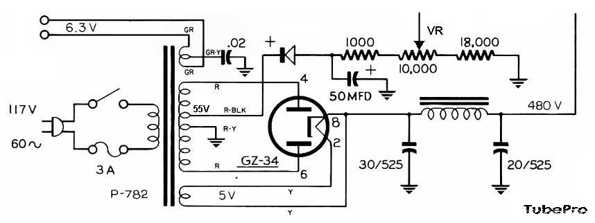
Other way of biasing sounds more interesting to me, as the original circuit is very simple and not that stable as the regulated one using transistors you’ve mentioned. Master J, from your point of view, how much negative voltage do you think should be derived from this original circuit to bias those KT88’s? (Considering from the PT specs that it is a 55vac tap)
here's the ckt:

Sorry sir, I hope I’m not getting much of your time here, sorry for the ff Qs:
Correct me if I’m wrong, should there be an approx -61.6 vdc when the 10-Kohm VR is at the center position? If that 55vac will be rectified to around -77.8vdc with the filter capacitor, 50uF.
As I remember in my early ohms law, (hehehe parang mejo kinakalawang na po kasi) with those resistive network, the circuit draws approx 2.68mA of current. And with VDT, voltage across the 18-kohm is approx -48.24v plus voltage @ 5-Kohm (which is the center of 10-Kohm VR) is approx -13.35v equals -61.59vdc.
Is this theorem also applicable here? Pki-correct nalang po based on your expertise.
Well if you have a better biasing circuit, would you mind sharing that to me, hehehe… Gusto ko po sir sana individual biasing for each KT88. Not like their original circuit, both output tubes share the same biasing adjustment.
Thanks much in advance Master J!
Mabuhay po kayo…
 ;)
« Last Edit: Aug 31, 2009 at 04:00 PM by Tube Pro »
UNIVAC: a device, which contained 20,000 vacuum tubes!

Offline JojoD818

  • Trade Count: (+147)
  • PinoyDVD Legend
  • *****
  • Posts: 14,558
  • Bring it on!
  • Liked:
  • Likes Given: 57
Don't let the interest in other possible circuits get the better part of you sir, the original circuit is a very good starting point already, you can modify this for individual biasing by making two identical negative rectifier circuits (along with their own cap, 1K, 18K resistors and adjustment pot), this way you can adjust them individually per tube.

As you have observed, the 1K - pot - 18K form a voltage divider for the negative bias psu section and that theorem on basic Ohm's Law is applicable for the negative biasing circuit, however, if you will take into account the two 100K resistors that branches to each KT88 and also factor the grid current of each output tube then Kirchoff's Law of Voltage and Current would be more appropriate to use. But let's not re-invent the MK3 just yet  ;D, what you must remember is that each output tube needs negative voltage at it's grid to maintain proper plate current, losing one will force that tube into full conduction and perhaps exceed it's operating parameters.

Build the amp and earn skill and confidence points while doing it, you'll surely make survivable mistakes but what's important is that you learn and understood why it was a mistake.


Offline Tube Pro

  • Trade Count: (0)
  • Collector
  • **
  • Posts: 138
  • It occupied 1,500 square feet and weighed 40 tons:
  • Liked:
  • Likes Given: 0
Don't let the interest in other possible circuits get the better part of you sir, the original circuit is a very good starting point already, you can modify this for individual biasing by making two identical negative rectifier circuits (along with their own cap, 1K, 18K resistors and adjustment pot), this way you can adjust them individually per tube.

As you have observed, the 1K - pot - 18K form a voltage divider for the negative bias psu section and that theorem on basic Ohm's Law is applicable for the negative biasing circuit, however, if you will take into account the two 100K resistors that branches to each KT88 and also factor the grid current of each output tube then Kirchoff's Law of Voltage and Current would be more appropriate to use. But let's not re-invent the MK3 just yet  ;D, what you must remember is that each output tube needs negative voltage at it's grid to maintain proper plate current, losing one will force that tube into full conduction and perhaps exceed it's operating parameters.

Build the amp and earn skill and confidence points while doing it, you'll surely make survivable mistakes but what's important is that you learn and understood why it was a mistake.


Thanks for the insights master J. ;)
You’re right, KVL and KCL would be more appropriate for this circuit or even the nodal analysis as well.
But before we get into this approach, from your point of view it’s better to use Dynaco’s original design as it is a good starting point for me as a tube beginner.
You mentioned that I need to make another negative rectifying circuit (along with the C, Rs and Pot) for the other tube so I can adjust them separately. Master J, how about the modification in the output circuit, should I split also the two 100-Kohm and connect each to the wiper terminals of the Pot? Then both cathode ( Pin # 8 ) of the KTs are connected to each other having an 11.2-ohm resistor to ground, should I disconnect that bridge and have another 11.2-ohm resistor for the other tube’s cathode?
To clarify, I encircled the parts in red:

I'm afraid of experimenting further as I am dealing with the lethal voltages, so there's no room for mistakes.
Thanks for all the warnings and instructions Sir!  8)
« Last Edit: Aug 31, 2009 at 06:47 PM by Tube Pro »
UNIVAC: a device, which contained 20,000 vacuum tubes!

Offline JojoD818

  • Trade Count: (+147)
  • PinoyDVD Legend
  • *****
  • Posts: 14,558
  • Bring it on!
  • Liked:
  • Likes Given: 57
Thanks for the insights master J. ;)
You’re right, KVL and KCL would be more appropriate for this circuit or even the nodal analysis as well.
But before we get into this approach, from your point of view it’s better to use Dynaco’s original design as it is a good starting point for me as a tube beginner.
You mentioned that I need to make another negative rectifying circuit (along with the C, Rs and Pot) for the other tube so I can adjust them separately. Master J, how about the modification in the output circuit, should I split also the two 100-Kohm and connect each to the wiper terminals of the Pot? Then both cathode ( Pin # 8 ) of the KTs are connected to each other having an 11.2-ohm resistor to ground, should I disconnect that bridge and have another 11.2-ohm resistor for the other tube’s cathode?
To clarify, I encircled the parts in red:

I'm afraid of experimenting further as I am dealing with the lethal voltages, so there's no room for mistakes.
Thanks for all the warnings and instructions Sir!  8)


Of course you should split the two 100K resistors, one for each grid that is. IIRC, in the original circuit, the output tubes conduct approximately 140mA (70mA per kt88) through the 11.2 ohm cathode resistor which makes an impressed voltage of 1.56V. Dynaco is fond of doing this because during those days, digital voltmeters are not that widely available and most analog meters have widely varied tolerances. So you will need to calibrate your meter with a fresh 1.5V battery and take note of that reading in your analog meter and that should be the reading you get when you bias your tubes. If you want to split the biasing of the lower and upper output tube then you must also split the cathode resistor physically (not it's value), one for each tube.

Now if you will still use another 11.2 ohm cathode resistor for one of the outputs, a 70mA current flow will produce 0.78V only. But if you want to maintain measuring a 1.56V when you bias your tube, then a cathode resistor of about 22 ohms is needed per kt88 tube.


Offline ATJr.

  • Trade Count: (+45)
  • PinoyDVD Legend
  • *****
  • Posts: 4,328
  • Leach Amp fan!
  • Liked:
  • Likes Given: 0
hi, i heard my name called....

initial bias adjustment is to allow you to check up your negative bias circuit....to be on the safe side, i would set it at the highest negative voltage initially, in your circuit, to the 1k side rather than the 18k side. check that there is indeed negative voltage there, never mind that it may be -100volts, as long as it is negative, you are ok.

remember that this amp was designed and manufactured at a time when moderns silicon rects were not yet common...

so are you getting the original irons? and original design power traffo? good luck...i am not online all the time, if you have further questions, you can reach me at [email protected]

good luck on your project. ;)
That's OK, you can like or dislike anything you choose. That's the wonderful thing about the freedom

Offline Tube Pro

  • Trade Count: (0)
  • Collector
  • **
  • Posts: 138
  • It occupied 1,500 square feet and weighed 40 tons:
  • Liked:
  • Likes Given: 0

Of course you should split the two 100K resistors, one for each grid that is. IIRC, in the original circuit, the output tubes conduct approximately 140mA (70mA per kt88) through the 11.2 ohm cathode resistor which makes an impressed voltage of 1.56V. Dynaco is fond of doing this because during those days, digital voltmeters are not that widely available and most analog meters have widely varied tolerances. So you will need to calibrate your meter with a fresh 1.5V battery and take note of that reading in your analog meter and that should be the reading you get when you bias your tubes. If you want to split the biasing of the lower and upper output tube then you must also split the cathode resistor physically (not it's value), one for each tube.

Now if you will still use another 11.2 ohm cathode resistor for one of the outputs, a 70mA current flow will produce 0.78V only. But if you want to maintain measuring a 1.56V when you bias your tube, then a cathode resistor of about 22 ohms is needed per kt88 tube.


Hi Master J, just have gone from a tight week long schedules kaya mejo natahinik sa makulit na pagtatanong.
Anyways, here again with questions :D
So there should be a 140mA current flowing to the 11.2 ohms and will split to both cathode pin of the tubes allowing 70mA on each branch to have the right bias. Voltage drop across that R is 1.56V as V=IxR, which is very much true with the 22 ohms in each tube’s cathode for an individual biasing.
Just noticed some PP tube amps schems used a lower value resistor on their cathodes, some are even directly connected to ground.
How about sir, if I use a 1-0hm resistor and instead of getting the 1.56v drop across it, I’ll adjust the pot to get a 70mV reading from a reliable high impedance digital volt meter? By then we’re sure that the desired 70mA current is flowing on each tube.
So which is better or best to use?
The 22-ohm with 1.56v bias or the 1-ohm with 0.07v bias?
Or just omit and connect the cathode to ground.  ???
How do these values (resistance) affect the circuit’s performance?
Is it true that with this cathode resistor in circuit will improve the amp’s specification with lesser THD?
UNIVAC: a device, which contained 20,000 vacuum tubes!

Offline Tube Pro

  • Trade Count: (0)
  • Collector
  • **
  • Posts: 138
  • It occupied 1,500 square feet and weighed 40 tons:
  • Liked:
  • Likes Given: 0
hi, i heard my name called....

initial bias adjustment is to allow you to check up your negative bias circuit....to be on the safe side, i would set it at the highest negative voltage initially, in your circuit, to the 1k side rather than the 18k side. check that there is indeed negative voltage there, never mind that it may be -100volts, as long as it is negative, you are ok.

remember that this amp was designed and manufactured at a time when moderns silicon rects were not yet common...

so are you getting the original irons? and original design power traffo? good luck...i am not online all the time, if you have further questions, you can reach me at [email protected]

good luck on your project. ;)

Hi Sir TonyT,

Thanks for joining the thread. ;) I know you guys are too busy as well as Master J, yet you are willing to share some good points and knowledge on your expertise.
Also thanks for giving this SAFE initial bias adjustment “highest negative voltage”, rather than setting the pot midway based on the original dyna manual, which is really less risky.
I’ve learned also from the master that without this negative potential will force the tube into full conduction and exceed its operating parameters and cause red plating.
For the irons…
I found some trannies on the internet which almost has the same specs as the original design, one from Hong Kong, Raphaelite and BEZ brands. Have you heard that? Any good reviews?
I also was trying to reach Sir Edrel Sison, whom I think is in line with this iron production, but hasn’t replied my PM yet. I read some threads here showing his expertise and some pics of his works. Sir Arnold who happens to be his kumpare gave his contact number already. I maybe calling him when I am free next time.
So where do you guys getting your power and output taffos?
Is it practical to buy Hammond traffos in terms of performance?
(price vs. quality) How about Chinese stuff?
Can you recommend one? I can also be reached thru my yahoo mail:
[email protected]
Salamat uli ng marami Sir TonyT! :D


Hope to hear more from you guys, more power!

 
« Last Edit: Sep 02, 2009 at 11:11 PM by Tube Pro »
UNIVAC: a device, which contained 20,000 vacuum tubes!

Offline edrel sison

  • Trade Count: (+32)
  • Collector
  • **
  • Posts: 447
  • Liked:
  • Likes Given: 18
I also was trying to reach Sir Edrel Sison, whom I think is in line with this iron production, but hasn’t replied my PM yet. 

sorry haven't been on line very often. you may also check some shops in HK. call me edrel na lang po. give me a ring when you are in town and i will be glad to show you sample irons.

Offline Tube Pro

  • Trade Count: (0)
  • Collector
  • **
  • Posts: 138
  • It occupied 1,500 square feet and weighed 40 tons:
  • Liked:
  • Likes Given: 0
sorry haven't been on line very often. you may also check some shops in HK. call me edrel na lang po. give me a ring when you are in town and i will be glad to show you sample irons.

Yes sure, sir.
As I've mentioned to my previous PMs to you, I'll just take my orders in December during my vacation, (as only 15kg is allowed for each Cebu Pacific passenger) and expect me to come to your place to see your samples. For the meantine I'll check around the shops in HK and China to get these trannies and compare the performance. :)
UNIVAC: a device, which contained 20,000 vacuum tubes!

Offline Tube Pro

  • Trade Count: (0)
  • Collector
  • **
  • Posts: 138
  • It occupied 1,500 square feet and weighed 40 tons:
  • Liked:
  • Likes Given: 0
This is it!
Got most of the passive components already. :D
Will post pics later of the step by step procedures.

Dear tube gurus,  ;) please assist me and provide some tips...  :)

TIA!
UNIVAC: a device, which contained 20,000 vacuum tubes!

Offline Tube Pro

  • Trade Count: (0)
  • Collector
  • **
  • Posts: 138
  • It occupied 1,500 square feet and weighed 40 tons:
  • Liked:
  • Likes Given: 0
Honestly, I won't be having this self-confident to build this 1st tube project without the valuable helps, tips and advises from the ff PinoyDVD tube experts:  ;)
Master J (JojoD818)
Sir TonyT
Edrel Sison

Maraming salamat po!

To start with, the passive components:

From Alexan (Mega Mall)


unfortunately, Alexan doesn't have 1/2-watt 1% tolerance metal film resistors, even in Shuhai China.
They just have 1/4w. :(
Sa Raon po ba meron, like in Deeco...etc..?
 ???
« Last Edit: Oct 03, 2009 at 10:36 PM by Tube Pro »
UNIVAC: a device, which contained 20,000 vacuum tubes!